Hello! I've got an assignment to draw a laboratory set-up diagram and some circuits. I decided to do it with Inkscape. Since I'm new and don't have many knowledge. So could anyone tell me how and if it's possible to fit lines on grids since I want perfect detail?
Thanks
Drawing a Circuit or Lab Set-up diagram
Re: Drawing a Circuit or Lab Set-up diagram
Yes, it's possible to "fit lines on grids". Although to be honest, I don't know exactly what you mean. And I don't know what "a laboratory set-up diagram and some circuits" is either. You might or might not be able to have perfect detail. Since I don't know exactly what you mean by that either, I'm not sure if Inkscape can do it. If you're talking about line drawings, Inkscape can give perfect detail. If you're talking about reproducing a photo, then no, Inkscape can't do that.
It sounds like you have a quite steep learning curve. I've found that the fastest way to learn Inkscape, is to follow some tutorials. Please see the links in my signature for the best learning resources that I know about.
It sounds like you have a quite steep learning curve. I've found that the fastest way to learn Inkscape, is to follow some tutorials. Please see the links in my signature for the best learning resources that I know about.
Basics - Help menu > Tutorials
Manual - Inkscape: Guide to a Vector Drawing Program
Inkscape Community - Inkscape FAQ - Gallery
Inkscape for Cutting Design
Manual - Inkscape: Guide to a Vector Drawing Program
Inkscape Community - Inkscape FAQ - Gallery
Inkscape for Cutting Design
Re: Drawing a Circuit or Lab Set-up diagram
Hi
Have a look at the extensions, Ependorf, Erlendmeyer, Tube, Thermometer found here.
If you are using Inkscape version 0.91 (or later) you have to edit the py files and change inkex.unittouu to self.unittouu for the extensions to work.
Chime back if you need help doing this.
The extensions will create these:
Good Luck!
( ͡° ͜ʖ ͡°)
RGDS
Ragnar
( ͡° ͜ʖ ͡°)
RGDS
Ragnar
Re: Drawing a Circuit or Lab Set-up diagram
Hi.
I've used Inkscape to draw schematics and wiring diagrams. Here is what I recomends for you to get clean colored lines** when exported to PNG:
**
A clean colored line in my opinion is a line that is either vertical or horisontal and the edges doesn't blur at all. Any line that have an angle that differ from 0 or 90 degrees and have a thickness that is not a whole number WILL have blurred edges.
I've used Inkscape to draw schematics and wiring diagrams. Here is what I recomends for you to get clean colored lines** when exported to PNG:
- Default units sets på px in Document Propertie dialog box (DPdb for short)
- Document width and Height should be set to whole number in DPdb.
- Use grid lines where Origin X and Origin Y is set to 0.5. I also prefer to check the "Show dots insteads of lines" because I think it looks better.
- The thickness of your lines should be whole numbers. For circles and round corners that doesn't really matters.
- When exporting to PNG, do always make sure that Export area=Page and dpi is set to 90. That is neccesary for dimension for the output image to match your drawing.
- With these settings, avoid using rectangles with no stroke - the edge in the exportet png will be 0.5 px offset to the missing stroke and will therefore look blurred by a half px. What you can do with rectangles with no stroke (assuming that they snap to a pixel) to avoid blur is to either to move it 0.5 px in both x and y direction, or you can apply a 1px wide stroke and reduce it's size by 1 px in both x and y directions.
**
A clean colored line in my opinion is a line that is either vertical or horisontal and the edges doesn't blur at all. Any line that have an angle that differ from 0 or 90 degrees and have a thickness that is not a whole number WILL have blurred edges.
Re: Drawing a Circuit or Lab Set-up diagram
Thanks for the replies guys. Got much useful info. But anyway it's impossible to fit. By the way brynn an example of a circuit is this http://i.stack.imgur.com/geioP.gif so I need an easy way to draw many lines on some standard distances. Tho the only way to do it with Inkscape is by measuring the distances myself (pixels,cm or whatever).
Re: Drawing a Circuit or Lab Set-up diagram
Hi
I reckon the reason you see this as impossible is that you are new to Inkscape, you will discover more and more possibilities as you learn Inkscape.
In inkscape there are (almost) always more than one way to get the result you want.
To give you just one example, to create evenly spaced wires (bus) you can;
a: draw the upper and lower wires and then with the two lines (paths) selected use; Extensions - Generate from Path - Interpolate
b: draw the upper and lower wires and then with the two lines (paths) selected combine the two (Ctrl K) then use the Path effects + Interpolate Subpaths
c: Draw one wire - duplicate (Ctrl D) then; either move manually by dragging or; use the Object Transform - Shift function.
d: Draw one wire - select the path - keep the left mouse button pressed, and tap the space-bar to "stamp" the rest of the wires - by stamping all in same place and then use the align tool (Ctrl Shift A) you can get a nice bus.
e: Draw one wire - select the wire and use Edit - Clone - Make tiled clones.
f: Enable the grid, set grid distance to fit your requirement, enable snapping to grid and draw manually.
g: Use guide lines, draw manually snapping to the guides.
h: Draw the IC's (Integrated Circuits) and use the Create Diagram Connectors to route the wires between the IC's.
I am sure there are a lot of other ways to do this as well.
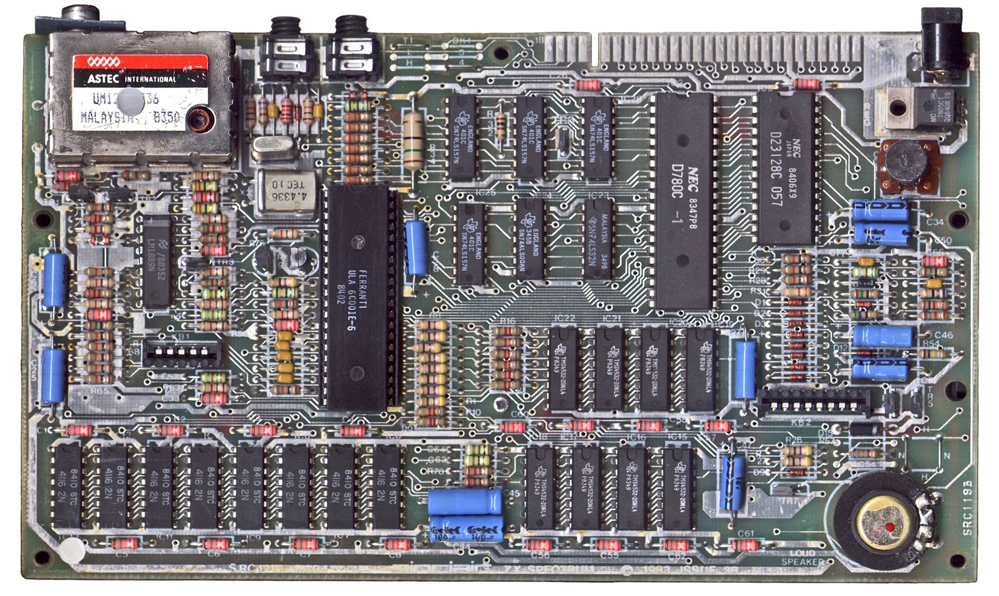
By the way - The schematics in your link is for a Sinclair ZX Spectrum. Spectrum - PCB
I had it's predecessor - a ZX81 with a whooping 1K of memory, later bought a 16K expansion module!
Still got it in working condition!
Learned some assembly programming on it's Z80 processor ages ago!
sonafab wrote:But anyway it's impossible to fit -
I need an easy way to draw many lines on some standard distances. Tho the only way to do it with Inkscape is by measuring the distances myself (pixels,cm or whatever).
I reckon the reason you see this as impossible is that you are new to Inkscape, you will discover more and more possibilities as you learn Inkscape.
In inkscape there are (almost) always more than one way to get the result you want.
To give you just one example, to create evenly spaced wires (bus) you can;
a: draw the upper and lower wires and then with the two lines (paths) selected use; Extensions - Generate from Path - Interpolate
b: draw the upper and lower wires and then with the two lines (paths) selected combine the two (Ctrl K) then use the Path effects + Interpolate Subpaths
c: Draw one wire - duplicate (Ctrl D) then; either move manually by dragging or; use the Object Transform - Shift function.
d: Draw one wire - select the path - keep the left mouse button pressed, and tap the space-bar to "stamp" the rest of the wires - by stamping all in same place and then use the align tool (Ctrl Shift A) you can get a nice bus.
e: Draw one wire - select the wire and use Edit - Clone - Make tiled clones.
f: Enable the grid, set grid distance to fit your requirement, enable snapping to grid and draw manually.
g: Use guide lines, draw manually snapping to the guides.
h: Draw the IC's (Integrated Circuits) and use the Create Diagram Connectors to route the wires between the IC's.
I am sure there are a lot of other ways to do this as well.
By the way - The schematics in your link is for a Sinclair ZX Spectrum. Spectrum - PCB
I had it's predecessor - a ZX81 with a whooping 1K of memory, later bought a 16K expansion module!
Still got it in working condition!
Learned some assembly programming on it's Z80 processor ages ago!
Last edited by ragstian on Mon May 25, 2015 5:07 pm, edited 1 time in total.
Good Luck!
( ͡° ͜ʖ ͡°)
RGDS
Ragnar
( ͡° ͜ʖ ͡°)
RGDS
Ragnar
Re: Drawing a Circuit or Lab Set-up diagram
"By the way brynn an example of a circuit is this"
Oh, see this masterpiece by Ragnar! http://inkscapecommunity.com/ic_gallery/index.php. Not exactly the same thing. But similar.
I do know the definition of "circuit", but a circle is one kind of circuit. A triangle might even be another kind. Or flow chart. Really healthy people work out at the gym with something called circuit training. And of course electrical circuit.....in this case electronic circuit. And I had no idea what kind of lab you meant - chemistry lab, computer lab, hospital lab, etc. (haha - evil mad scientist lab!)
"Tho the only way to do it with Inkscape is by measuring the distances myself (pixels,cm or whatever)." So you want to be able to enter the distance you want, and have Inkscape draw it?. I think CAD type programs typicallly provide that kind of feature. (although I'm not really sure about that, definitely not from personal experience) But as Ragnar said, there are several easy ways to draw lines like that with Inkscape. Although....
When I look at that GIF full size, I can see that many of the lines have variable widths. I'm not sure if you want quite that much precision, or if those variable widths are a result of poor raster quality..... In some places it almost looks like the kind of artifacts that older photocopy machines used to produce. Or maybe some of those lines are hand drawn?
Even with an experienced Inkscape user, drawing that whole diagram would take some hours. Actually, I would enjoy a challenge like that....except I just don't have time right now. Anyway, you'll want to check out the manual for Snapping and Grids and maybe even Guides. With 0.91, the guides have been improved (they're awesome!). Now we can have different colored guides, and I think labels for the guides too.
Basics - Help menu > Tutorials
Manual - Inkscape: Guide to a Vector Drawing Program
Inkscape Community - Inkscape FAQ - Gallery
Inkscape for Cutting Design
Manual - Inkscape: Guide to a Vector Drawing Program
Inkscape Community - Inkscape FAQ - Gallery
Inkscape for Cutting Design
Re: Drawing a Circuit or Lab Set-up diagram
Thank you very very much brynn! Seems like i was wrong about the "impossible" thing I mentioned. I read some of the manual sections and understood some things. Also your example above (the steps u mentioned) was very helpful! I'll try to get more into Inkscape cuz I underestimated it.
By the way, I checked that Launchpad as well as other of your works and they are amazing! Good job!
By the way, I checked that Launchpad as well as other of your works and they are amazing! Good job!