Drawing Junction Views

Post questions on how to use or achieve an effect in Inkscape.
Palmnoah
Posts: 3
Joined: Sat Jul 28, 2012 1:13 pm

Drawing Junction Views

Postby Palmnoah » Sat Jul 28, 2012 1:28 pm

Hi,

Inkscape newbie here. I'm part of a voluntary mapping group from Malaysia where we drive around roads collecting tracklogs and points of interest so tourists who visit our country can travel using a GPS without getting lost.

We're in the process of drawing Junction Views which aid the user to navigate through complicated junctions. A junction view typically looks like this:

200009-garmin-nuvi-885t-junction-view.jpg
200009-garmin-nuvi-885t-junction-view.jpg (52.05 KiB) Viewed 2140 times


Can someone show me or point me in the right direction on how to draw a similar image from photos such this:

Image

I've tried Path > Trace Bitmap but prefer manual hand tracing and have so far gotten as far as tracing the outline of the road with the Draw Freehand Lines tool:

20120728 Inkscape JCV tracing roads.jpg
20120728 Inkscape JCV tracing roads.jpg (16.04 KiB) Viewed 2140 times


Here are a few questions:

1) How do I prevent from tracing outside the picture?
2) How can I draw the dashed line in perspective view (wider when near and thinner when far), particularly how to make the vector line dashed?

I finally would like to save the graphics as SVG so the junction views can be resized freely.

Thanks for any help.

Noah
malsingmaps.com
masmap.org

User avatar
brynn
Posts: 10309
Joined: Wed Sep 26, 2007 4:34 pm
Location: western USA
Contact:

Re: Drawing Junction Views

Postby brynn » Sun Jul 29, 2012 4:02 am

Image
Welcome Noah!

Oh, what a fun project! You'll have to forgive me, not being familiar with GPS. Do some GPS devices have a view screen for images like this? The only GPS I've seen have no visual cues, just the electronic voice (audio only). But I don't get around much, so...well anyway, just so I understand. Will this show up in the device's view screen, or will there be something like a little guide booklet that goes along with the GPS audio instructions?

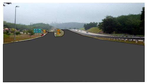
The first thing I'd like to mention, is about using the Pencil/Freehand tool. Depending on the configuration of settings, that tool can potentially generate an excessive amount of nodes. The problem with excessive nodes, besides making editing more difficult, is that it can bloat the file size. If you are only drawing the road, signs, guardrail, it probably won't matter. But if you plan to draw the trees, for which I guess you might use a filter, the file size might start to matter (because filters also can bloat the file size,). I would suggest setting Smoothing of Pencil/Freehand tool no lower than 25. (For myself, I would use the Pen/Bezier tool. You could get a nice smooth curve, like the right edge of the main roadway, in your photo, with just 3 or 4 nodes.)

For your first question, how to prevent drawing outside the border, there may be a variety of solutions. The simplest is probably to make the Inkscape page border match the photo's border. Document Properties > Page tab, or select the photo alone, then go to Doc Prop > Page Tab > Page Size > Custom Size > Resize page to content. After the page border is set properly, then you can enable Snapping. Set snapping to page borders. Now as you draw lines, with the Pencil/Freehand tool, when you get close to the border, you'll see a tiny X flash on the border. Let go of the mouse when you see the X, and the end of the line will jump over to that point. It's a similar scenario with the Pen/Bezier tool, except that you won't be holding the mouse button. When the mouse gets close to the border, the X will flash, then you click, and the node will be placed on the border.

If you're just going to draw the roadway and related things, and not the trees, that snapping solution will work great. But if you draw the trees, and depending how you draw the trees, you might need to look for a different solution -- perhaps clipping (http://tavmjong.free.fr/INKSCAPE/MANUAL/html/Clip.html). Actually you could use clipping for the whole darn thing, and forget about snapping. And I suspect that decision comes from your personal preference. Some people find snapping frustrating, and indeed it can be tricky in certain situations (http://tavmjong.free.fr/INKSCAPE/MANUAL ... pping.html).

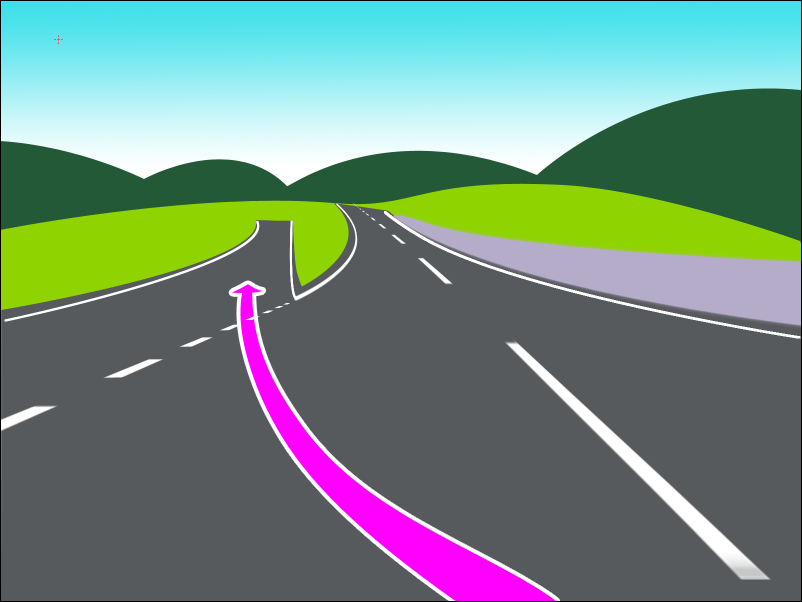
And finally, the perspective on the lines on the road -- you could trace the lines, like you've traced the roadway. Otherwise there are a few different ways to approach drawing them. And actually, I'm going to let someone else explain that. I could draw it myself, but there was a question about this that I remember, maybe....oh, a year or 2 ago, I guess. The solutions offered in that topic were very clever, and very effective. I'll look for it, but I probably won't find it. But the people who answered that old topic, are still active in the forum, and should be around soon (probably they'll post right before I post this -- seems to be happening a lot lately :mrgreen: )

Have fun drawing! :D

Palmnoah
Posts: 3
Joined: Sat Jul 28, 2012 1:13 pm

Re: Drawing Junction Views

Postby Palmnoah » Mon Jul 30, 2012 1:55 am

Hi brynn,

Thanks for your reply.

Yes, these SVG photos popup just before a junction to aid the GPS user on which junction to take. Sometime lines and arrows confuse the user even in 3D mode so a junction view photo helps, especialy for complicated intersections.

Here's what I want to achieve with Inkscape:

JCV.png
JCV.png (118.83 KiB) Viewed 2086 times


The hills and roads were traced using a bevier tool and filled with colour while the road lines, solid and dashed, used the line tool which was later warped. But this was done with Adobe Photoshop. I want to achieve a similar finish with Inkscape as not all our volunteers have PS.

Can this be done easily with Inkscape?

Cheers.

Noah

User avatar
brynn
Posts: 10309
Joined: Wed Sep 26, 2007 4:34 pm
Location: western USA
Contact:

Re: Drawing Junction Views

Postby brynn » Mon Jul 30, 2012 1:59 pm

Oh yes, quite easily!
I would use snapping to page borders and corners, to keep drawing inside. But you could draw outside window, and then use clipping to sort of cut off the excess (although note that it's really more covered up than cut off).

I would still like someone else to address the gently curved, dashed lines with perspective, if possible. It can be done better than what appears in your last screenshot. But if that's acceptable for you, then it appears you've found a way to do it. If no one else wants to, I can probably hack out a way. But I've seen some nice examples in an old topic. Unfortunatley, I can't find it. If I recall, it was done with pattern along path. Ok, I'll try to work something up, and post it shortly.

User avatar
brynn
Posts: 10309
Joined: Wed Sep 26, 2007 4:34 pm
Location: western USA
Contact:

Re: Drawing Junction Views

Postby brynn » Mon Jul 30, 2012 4:53 pm

Ok, well I found a way, but it may not be the best way. Note that this should probably only be used for the dashes that are distinct in the original image. If you look at the photo, about halfway up the road, the dashes are all merged in to a faded single line. But for the ones in the foreground, this should work.

1 -- Draw a rectangle, that's width is as narrow as at the top of the foreground dashes, and length, not more than 2 or 3 times the width. Then do Path menu > Object to Path.
2 -- Select with Node tool, select 2 end nodes, and click "Break path between selected nodes" button, then do the same for the other end. Now you should be left with 2 parallel, vertical lines.
3 -- Path menu > Break apart
4 -- Select all 4 nodes, then click "Insert nodes into selected segments" button 4 or 5 times, or maybe 6.
5 -- Deselect everything. Select one line, do Ctrl + A, then hold down the Alt key, grab the bottom node, and drag the line downward until it's twice the length you want.
6 -- Select all the nodes in the other line, and do the same thing, except after you drag downwards, and before you release the node, drag it over horizonally, until the width is equal to twice the width of the bottom dashes in the photo. So now, that line will appear to sort of lean over towards the other, at the top. They should be twice as long as you need. At the top, the space between them should be the width of the foreground dashed road line at the top. At the bottom, it should be twice the width of the dashed road line at the bottom.
7 -- Now you'll notice, when the lines are selected with the node tool, that the nodes are spaced more widely apart in the middle, than they are at the top and bottom. Select both lines (use Shift for multiple selection) and draw a selection box around the bottom half of both lines, which selects the bottom half of all the nodes. then Delete them.
8 -- Now to make the curve. At first, you can select all the nodes in both lines, hold the Alt key, grab one of the nodes halfway along one of the lines, and drag to the right, to start to make the curve. It will not make a very smooth curve.
9 -- For the next couple of steps, you'll want to select nodes in horizontal pairs. Or in other words, if you select the node 2nd from bottom on one line, also select the 2nd node from the bottom of the other line. Then they will move together. So you can move pairs of nodes, to smooth out the curve.
10 -- At some point, you may need to select individual nodes, to tweak their handles, to smooth out the lines, to make a smooth curve. But try to keep the nodes so that they are roughtly horizontal to each other.
11 -- Now because of the node sculpting behavior, the nodes are spaced in somthing remotely resembling the perspective you need. You can use the nodes spacing as a guide, to place new lines, drawn from one node on one line, to the comparable node on the other line.
12 -- Use the Paint Bucket tool to fill the spaces with white, while leaving alternate spaces unfilled.
13 -- When they're all filled, you can either delete the original lines, or make them transparent.

So, as you can see, this is sort of a hack way of doing it. I just can't remember the fancy and very clever way that I've seen, somewhere in the forum, but that I can't find.

User avatar
Maestral
Posts: 982
Joined: Sat Aug 27, 2011 7:10 am

Re: Drawing Junction Views

Postby Maestral » Mon Jul 30, 2012 10:11 pm

If you have difficulties with tracing perhaps you could look up for dev builds, where Powerstroke is available.

- That way you could easily create a "lane line", adjust it`s width to perspective and then convert it to path. It could have a bit too many nodes, which could slow you down and choke you computer, so simplify it (Path/Simplify).
- Create two rectangles (just fill, no stroke), landscape oriented, where first ones height and position fits the closest gap on the lane and the other one fits the most distant gap on the line. Adjusting the settings of interpolation (Extensions/Generate from Path/Interpolation) should create appropriate number, size and variable heights of rectangles which should be also converted to paths later on. While all rectangles are selected, unify them all into one object (Union) and then simply cut the previously created "lane line" with it (Difference).

Powerstroke is not the must, you could create "lane line" with Pen tool, but it`s just a matter of skills. However, I would still use those rectangles for creating dashed "lane line" in perspective, rather then fine tuning perspective of regular dashed line.
:tool_zoom: <<< click! - but, those with a cheaper tickets should go this way >>> :!:

Palmnoah
Posts: 3
Joined: Sat Jul 28, 2012 1:13 pm

Re: Drawing Junction Views

Postby Palmnoah » Tue Jul 31, 2012 1:51 am

Oh dear brynn, that sounds really complicated. However, I shall give it a go. Wish me luck!

User avatar
brynn
Posts: 10309
Joined: Wed Sep 26, 2007 4:34 pm
Location: western USA
Contact:

Re: Drawing Junction Views

Postby brynn » Tue Jul 31, 2012 3:30 am

Well, it's one of those things that is much easier to do, than to instruct. I did it myself in less than 5 minutes, but writing it all out makes it look worse. Oh, correction -- I did all the lines in less than 5 min. but it would take probably that much more time to fill the spaces, and do node edit as necessary.

And again, for some reason, I keep thinking there's some more automated way to do it. Instead of dragging the nodes to make the curved lines, you could probably use the Bend LPE. But it would take me so many more words to explain it, lol!

Maestral, I thought of Interpolation. It would make the dashes/rectangles gradually smaller in size. But then I couldn't figure out how to make the interpolated rectangles in a curved line....unless.... I wonder if you did the interpolation, and after that, if you could apply the Bend LPE??

Ok, hold on Palmnoah -- we may have come up with a better way! Let me experiment, and I'lll post again :D

Edit
Well, unfortunately, that was a bust. The heart of the problem, the way I see it, is the combination of the curve and the perspective results in the dashes/rectangles, or actually they're trapezoids which change in both size and shape, and even orientation, as you move from closest to horizon (near to far?). I think to make this technically precise, someone would need to write an extension, with all the proper math and stuff. I think, at least with my current knowledge of Inkscape, this can only be approximated. And there may well be a few different ways to approximate it, and it's truly a matter of personal preference, as to which way you go. I tend to enjoy node editing. Others might prefer path operations.

Oh geez, now I have another idea, lol. I'll post again, if I have any luck :D


Return to “Help with using Inkscape”