[solved] transformation matrix

Post questions on how to use or achieve an effect in Inkscape.
Lazur
Posts: 4717
Joined: Tue Jun 14, 2016 10:38 am

[solved] transformation matrix

Postby Lazur » Sun Oct 06, 2013 11:45 am

Working on an axonometric construction.
The plan is to have a dimetric projection, with the x, and y axises placed in 41° and -8° to horizontal.
Something like this:
a3.png
a3.png (32.09 KiB) Viewed 6724 times

I created groups of paths that I would map to the horizontal plane.
I want to avoid the use of the envelope extension as that opens the closed paths unecessarily and creates double nodes.
Also, it's much faster to just skew and scale the parts to the right sizes.

Figured out how to input the right values to the transformation matrix panel to create a close result.
Unfortunately when I compare a square the same size of the horizontal plane transformed with a matrix to the right size,
I cannot have the EXACT same size I want.

My question is, how to solve this?
Is there a way to edit some pref sections to increase the number of input digits to the transformation panel,
or does it have to do something to the implementation that it cannot be made more accurate?


Edit:
it's a bit theoretical as I could get the exact size since by performing scaling first and then skewing.
But why to have a matrix tool if it is not as accurate?

User avatar
ragstian
Posts: 1181
Joined: Thu Oct 11, 2012 2:44 am
Location: Stavanger-Norway

Re: transformation matrix

Postby ragstian » Tue Oct 08, 2013 11:04 am

Hi

This has been a topic earlier; viewtopic.php?f=22&t=13790

"Hard-Coded" values and limits in dialogs are a pain in the neck.
Luckily for all extensions it's relatively easy to edit the dialogs to suit your needs but not so with the "built-in" dialogs.

Maybe you can file a bug report or request on the developers forum to get a remedy in the next version? http://inkscape.org/mailing_lists.php

A workaround is to use the XML editor; from Tavmjong Bah's book;

Transforms with the XML Editor;
    Full control over the transformation of an object is available through the XML Editor dialog (Edit → icon XML Editor... (Shift+Ctrl+X)). Selecting an object in the document window will bring up the object's attributes in the XML Editor dialog. Any transform an object is subject to is described by the transform attribute. A transform can be of type “translate”, “scale”, “rotate”, “skewX”, “skewY”, or “matrix”. In most cases, the transform will be of the “matrix” type. A matrix entry contains the Transformation Matrix in the order (A, B, C, D, E, F) where (ACE) is the first row of the matrix.

    One thing to note is that the matrix describes a transformation with respect to the User Coordinate System which, if an object is not in a Group, is equivalent to the SVG coordinate system (Initial View Port) where the origin is at the top-left corner of the page (in contrast to the screen coordinate system where the origin is at the bottom-left of the page). See the SVG standard for more details.


Good Luck
RGDS
Ragnar
Good Luck!
( ͡° ͜ʖ ͡°)
RGDS
Ragnar

User avatar
druban
Posts: 1917
Joined: Fri Nov 20, 2009 10:48 pm

Re: transformation matrix

Postby druban » Tue Oct 08, 2013 1:14 pm

Hi Ragnar and Lazur, I think that Lazur is saying that he IS trying to use the transformation matrix but the results are not precise enough, perhaps because of rounding errors? Both of you are pretty deft programmers are you not, can you throw together a matrix transformation extension that does not do any rounding or uses more places of precision.
Your mind is what you think it is.

Lazur
Posts: 4717
Joined: Tue Jun 14, 2016 10:38 am

Re: transformation matrix

Postby Lazur » Tue Oct 08, 2013 8:24 pm

Thank's for the answers!
Thinking it over it might have been the way to solve this by the xml editor.
I just wasn't sure of it.
Tried it with simple paths but there no transformation data appeard in the xml editor after using the transformation matrix through the panel.
I should have tried it with groups as there it appears.
But would raise other problems with translation values.
The original object would have already a translation value, and, by copy/pasting
the right transformation values for a simple mapping would have produced a confusingly shifted result.

Good idea with the extension, but I never had luck with creating them.
Even if I had a new extension that I made by copy/pasting from existing ones, inkscape refused to open.

For an extension alike, it would only be for mapping to paralelograms so
it would be much better if the input data would refer only to the position of the "new origo",
and two digree values and two scale values,
or a forced one containing coordinate values of the three points of the new base vectors.
I'm guessing a simple path could serve as an imput with at least three nodes,
but it could be confusing with finding the first node of the path and the direction of it for a desired mapping.

User avatar
ragstian
Posts: 1181
Joined: Thu Oct 11, 2012 2:44 am
Location: Stavanger-Norway

Re: transformation matrix

Postby ragstian » Tue Oct 08, 2013 11:29 pm

Hi.
Druban;
Both of you are pretty deft programmers are you not, can you throw together a matrix transformation extension that does not do any rounding or uses more places of precision.

Good idéa! (Why did'nt I think of that?)

Lazur;
Is this something you would use? (Not much point in investing time making something that's never used.)

Quote from Jerry Pournelle (from BYTE magazine (remember that?) Chaos Manor column and now Circuit Cellar Magazine);
My favorite programming language is solder!

RGDS
Ragnar
Good Luck!
( ͡° ͜ʖ ͡°)
RGDS
Ragnar

Lazur
Posts: 4717
Joined: Tue Jun 14, 2016 10:38 am

Re: transformation matrix

Postby Lazur » Wed Oct 09, 2013 2:00 am

I used the transformation panel with a scaling and with a skewing after,
then used the align and distribute panel.
For 48 axonometric parts like on that image, and the time factor was reasonable with it.

Not sure of how useful it would be.
It would really give a boost for drawing in axonometry if any manual imputs were refused to the minimum.
Like the previous description would take too many manually counted imput factors.
Maybe because I had the existing method on my mind.

Because, for example if you could define the origo of the axises,
three digree for each axises, and scale factors,
that all could be stored like in the transformation panel,
and you could choose on which base plane you want the object to be mapped to, then
it would end up in a more handy panel for constructing.

In other cases a simple map to paralelogram-triangle- similar to the envelope extension would be better.

I would use it more often then like rendering the current gears I guess.
Another guess would be from me that creating an extension wich creates correct evolvent tooth profiled gears would make a better use
-more of cad like feature for the mechanical field.

Lazur
Posts: 4717
Joined: Tue Jun 14, 2016 10:38 am

Re: transformation matrix

Postby Lazur » Wed Oct 09, 2013 3:05 am

Created this as a pd image at openclipart:
SVG Image

description wrote:For some design I was working in dimetry, depicted with this image.
Dimetry refers to that two of the axises scale factor is the same.
That description covers a large variety of axonometric views though.
The scale factors and the angles I chose result that if you mirror the y axis along x axis, you will get z axis.

There are similar dimetry-s that are used more often, like the so-called
conventional axonometry.
Here is an image of that (original author unknown).
Image

Another commonly used one has it's axises at 97°; 131,5°; 131,5°,
and some may even use different scale factors too.

To me this one seemed a more trivial choice.

Image drawn with inkscape.
There are three invisible planes included in the svg, to make mapping of objects easier.


Will create another image(s) showing how to set the transformations right to map to the base planes.

Lazur
Posts: 4717
Joined: Tue Jun 14, 2016 10:38 am

Re: transformation matrix

Postby Lazur » Wed Oct 09, 2013 7:30 am

Here is what I figured out with the transformational matrix:
SVG Image

ragstian wrote:...
A workaround is to use the XML editor; from Tavmjong Bah's book;

Transforms with the XML Editor;
    ...In most cases, the transform will be of the “matrix” type. A matrix entry contains the Transformation Matrix in the order (A, B, C, D, E, F) where (ACE) is the first row of the matrix.
    ...


Tried to imput more accurate numbers through the xml editor but it all seems messed up:
it results in a horizontally mirrored object than if the values typed in the transform object panel.

Even if mirrored back, it doesn't seem to match with the desired shape.
Are those values counted wrong, or it's all that much inaccuracy?


By the way on the useage, it would be a connect between inkscape and blender.
Unfortunately I have no idea on the blender part too, as created a topic on that at blenderartists and noone replied yet.
http://blenderartists.org/forum/showthread.php?307699-Camera-setting-up-problem

User avatar
ragstian
Posts: 1181
Joined: Thu Oct 11, 2012 2:44 am
Location: Stavanger-Norway

Re: transformation matrix

Postby ragstian » Wed Oct 09, 2013 4:05 pm

Hi

I am a little puzzled at your values for the transformations.

Is your figure of the XYZ axes (the red, green and blue) from before the transformation or after?

The degree values given in examples on the net (your 98° - 131° - 131° ) shows the angles to be used for drawing on a 2d plane (paper).
My understanding (which might be incorrect - has happened before!) is that these values can not be used directly in transformations in Inkscape as the "UP vector" will then be tilting!
I might have misunderstood your explanation. :)
(I made a short video in POVray to convince myself) https://www.dropbox.com/s/wqwj9wtns2i6qxx/video.mpg
(In the video the transformation order is; 98° around X-Axis - then 131° around Y-Axis followed by 131° around the Z-Axis.)

To get isometric projection in blender you can turn "perspective" off! - Same in POVRAY where you specify; camera = isometric
Example file plus basis for animation from this site - go explore - it's a goldmine! http://www.f-lohmueller.de/index_d.htm
projection_Perspective.png
projection_Perspective.png (152.9 KiB) Viewed 6481 times

projection_isometric.png
projection_isometric.png (122.9 KiB) Viewed 6481 times


In Inkscape the transformations are all "added" up, I had problems getting it right in XML editor until I removed earlier transformations.

Some useful (or not) info;
http://home.comcast.net/~tamivox/redbear/axono/index.html
http://www.petercollingridge.co.uk/interactive-svg-components/isometric-projection
http://users.tpg.com.au/rivit/rvt-simcity-articles2.htm

RGDS
Ragnar
Good Luck!
( ͡° ͜ʖ ͡°)
RGDS
Ragnar

Lazur
Posts: 4717
Joined: Tue Jun 14, 2016 10:38 am

Re: transformation matrix

Postby Lazur » Wed Oct 09, 2013 5:38 pm

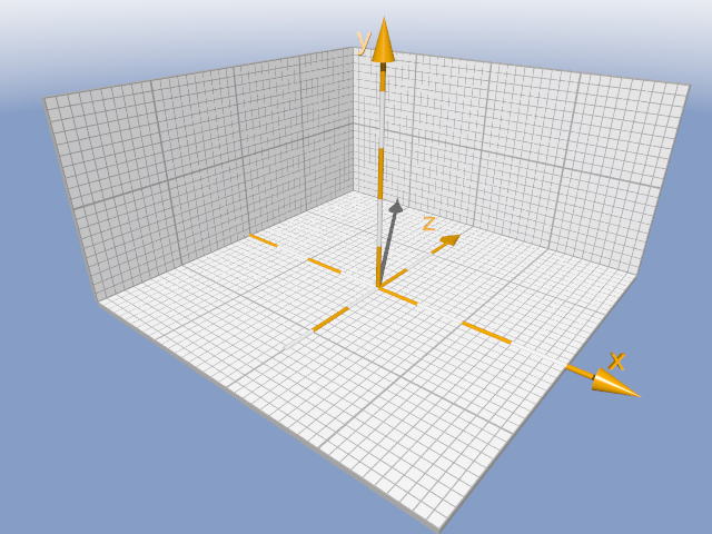
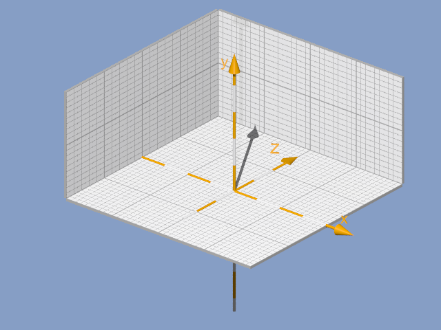
The axises shown are as they would look in 2D.
The angles written are showing merely how those axises would look on a 2D plane -paper-.
With the given scale factors it is not an orthogonal axonometry per se.
There are some similar dimetries with scale factors making it for an orthogonal view,
but this uses qx=0,5, xy=qz=1.
Like if it was all done on paper, those values could be constructed much easier.
While it IS close to an orthogonal view in look.
It is a bit illogical to give scale factors for the axises in orthogonal axonometry by the way.
Here is an example of an orthogonal projected dice:
http://www.math.bme.hu/~zlangi/descriptivegeometry/orthogonal_axonometry.pdf
If that was the goal, I would have asked for rotation angle values to write into the render 3D polyhedrons extension.
Which would be a too complicated way of drawing things in inkscape.

I know I can set a camera to be ortographic in blender, but these are different axonometric projections.
At that blenderartist topic I described an ugly solution for doing it.
For example, creating a military perspective would be
of setting the camera like in (0;-15;15), with a rotation value of (45°;0°;0°),
and scaling the model in x dimension with 0,707 factor.
But I'm not sure if the shadows would turn out right in cycles.
Also scaling the model and setting the camera for this dimetric look is a bit problematic that way.

At the same post I quoted the wikipedia's projection example's povray source file
Image

Code: Select all

#case (2)       // dimetric                #local cam_area =       2;
                #local cam_loca =       -z * cam_dist;
                #local cam_dirc =       +z;
                #local cam_rgvc =       +x * cam_area;
                #local cam_upvc =       +y * cam_area/cam_aspc;
                #local cam_tran = transform
                {
                        rotate          +x * asind(tand(15))
                        rotate          +y * 045
                        translate       +y * cam_move                 }

I am not sure though if it doesn't describe an orthogonal projection.
With the "oblique" -military perspective- projected models the different scale factors are more evident.
Which are not displayed right here in the forum,the image is way too big for that:
http://upload.wikimedia.org/wikipedia/commons/archive/4/41/20091120003734%21Graphical_projection_comparison.png

Sticking here with the original inkscape purpose: how to construct drawings in this dimetric axonometry.
By drawing only in 2D.
Let's say I have the side and top views drawn before, that I would like to transform
as they were on the actual xz and xy planes.
That means I have to "map" those somehow to these planes.
So figured out these transformation values, to be used on each of the views.
Actually this won't affect the "up" to be tilted.
I cannot recall which description of transformation matrix I saw,
but all those values can be checked on the xy, xz, yz plane's paralelograms.
They all have a value of x and y sizes of the path's right segments, with right senses.
Not mentioning again that those senses need to be changed if typed through the xml editor, as if not it produces a mirrored result.
And the fact that unfortunately even with those values the result is far from being accurate.

Will get together what transformations worked instead of the transformation matrix.
It is a bit more complicated as with the scale and skew values length dimensions were added.
The reason why an extension would be a boost for mapping many different sized objects without grouping them together, one by one, accurately.

Lazur
Posts: 4717
Joined: Tue Jun 14, 2016 10:38 am

Re: transformation matrix

Postby Lazur » Sun Oct 13, 2013 12:20 pm

So here it is:
SVG Image

If you have a square with it's side being "a" long, after transforming it with these values, they will be turned to the right shapes.

Here is a part of the drawing:
Image
-a bit larger rendering if you click on it-

All axonometry drawing done in inkscape.
Hell of a work and there are some parts that I may create another topic for.
(By the way this is just some part to illustrate what to be programmed later on with those cassini ovals for that letter calligraphy started waaay back...
http://www.inkscapeforum.com/viewtopic.php?f=20&t=14017
http://www.inkscapeforum.com/viewtopic.php?f=34&t=14056)

Lazur
Posts: 4717
Joined: Tue Jun 14, 2016 10:38 am

Re: transformation matrix

Postby Lazur » Mon May 04, 2015 6:34 am

Just found out there is an extension covering these transformations:
https://bugs.launchpad.net/inkscape/+bug/1362534


Return to “Help with using Inkscape”