preparing large areas for engraving via HPGL

Post questions on how to use or achieve an effect in Inkscape.
DubplateDerek
Posts: 5
Joined: Tue May 21, 2013 3:27 am

preparing large areas for engraving via HPGL

Postby DubplateDerek » Fri May 31, 2013 8:29 pm

Hi All,

I'm scratching my head trying to prepare some designs in Inkscape that will be exported as HPGL plt files and used to engrave aluminium front panels for audio equipment.

The bit I'm stuck on is how to ensure that the cutter head covers areas rather than single fine lines.

The issue is that I'm trying to recreate is a feature of Corel Draw that is detailed in these instructions :

http://www.frontpanelexpress.com/filead ... s/HPGL.pdf

Specifically this :

To fill your object, all inner lines are created with the contour To Center feature. The
Offset of the lines should be spaced properly to avoid gaps. Gaps can cause burrs and
poor milling results. Using an end milling cutter, select half the tool width for the offset.
Engraving tools have a further reduced Offset, because they are tapered.
Optimal offset values:
Tool Offset
Engraving tool 0.2 mm 0.07 mm
Engraving tool 0.4 mm 0.15 mm
End milling cutter 0.6 mm 0.30 mm
End milling cutter 0.8 mm 0.40 mm
End milling cutter 1.0 mm 0.50 mm
End milling cutter 2.0 mm 1.00 mm
End milling cutter 2.4 mm 1.20 mm
End milling cutter 3.0 mm 1.50 mm
If your graphic contains more then one object and you want to fill between the two,
select both and choose Arrange and Combine. Now fill your combined object To Center
with the appropriate Offset as mentioned above. For graphics using multiple tools select
different color lines. Each color represents one milling tool


Is there an Inkscape equivalent for this 'Contour to centre' option in CD? I have had a decent hunt about both in Inkscape and online and can't seem to see anything that does the same.

In fact, in my searches online there don't seem to be many people using Inkscape for panel design at all really, or have I missed you all?!

Cheers

DD

Lazur
Posts: 4717
Joined: Tue Jun 14, 2016 10:38 am

Re: preparing large areas for engraving via HPGL

Postby Lazur » Fri May 31, 2013 9:40 pm

There is an inset function in the node panel that can produce right results if set right previously in the preferencies panel.
Press Shift+Ctrl+P to set the step size. You can set that only in pixels,
so remember that inkscape uses 90 dpi, thus 90 pixels are an equal of 25,4 mm.
That means, for 1mm steps it will have to be set to 3,543 pixels.
You can access the insetting by pressing Ctrl+Shift+8.
Before insetting, duplicate the paths.

DubplateDerek
Posts: 5
Joined: Tue May 21, 2013 3:27 am

Re: preparing large areas for engraving via HPGL

Postby DubplateDerek » Fri May 31, 2013 11:36 pm

Thanks man, that's really helpful!

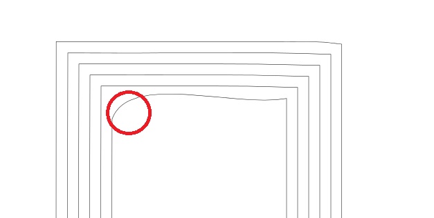
One other question though as I've encountered another stumbling block. Even if I start with a path which has sharp, 90° corners, by the 5th or 6th duplication and inset of the path it starts to go wavy. This makes it very hard to control the precise distances between the paths that the engraving tool will take, which of course means there's a risk that some parts of a letter may not be engraved.

See the attachment which illustrates what I mean. Is there any way to stop this happening?

In case it makes a difference, I'm going with an inset / outset value of 0.24px which is correct for an offset of 0.07mm for a 0.2mm engraving tool.
Attachments
inset.jpg
inset.jpg (17.03 KiB) Viewed 1950 times

Lazur
Posts: 4717
Joined: Tue Jun 14, 2016 10:38 am

Re: preparing large areas for engraving via HPGL

Postby Lazur » Sat Jun 01, 2013 12:28 am

The tool works fine here.
It seems that your basic path had more nodes than 4 and you simplified it -as with pressing Ctrl+L-.
Attachments
inset1.svg
(4.58 KiB) Downloaded 188 times

User avatar
ragstian
Posts: 1181
Joined: Thu Oct 11, 2012 2:44 am
Location: Stavanger-Norway

Re: preparing large areas for engraving via HPGL

Postby ragstian » Sat Jun 01, 2013 12:54 am

Hi Lazur URH.

The inset function fails to work correctly for small objects where "strange things" happen.
I reckon it's due to limited accuracy in the "internal calculations" performed,
maybe using "floats" instead of "longs" - to hold the node's values - in the code.
The inset is erratic for small objects in both stable and dev versions.

RGDS
Ragnar
Good Luck!
( ͡° ͜ʖ ͡°)
RGDS
Ragnar

Lazur
Posts: 4717
Joined: Tue Jun 14, 2016 10:38 am

Re: preparing large areas for engraving via HPGL

Postby Lazur » Sat Jun 01, 2013 1:48 am

A-ha!
Second checked that, it appears when one dimension is below 5 pixels.

As the inset is out there are another two workarounds:

A less accurate by dynamic offsetting.
Checked that, the size don't limits it.
So a not-so accurate, but working method can be insetting duplicants until it reaches the critical size,
then dynamic offsetting a duplicant of that for the remaining lines
or if possible drawing the smallest sized line by a dynamic offset of a duplicant,
then using the interpolation extension to draw the lines in between.
Before the interpolation the dynamic offset has to be converted to path,
then changed it's direction, flipped, and use interpolation method 1.
About 8-9 interpolation steps produces the parallels with the aproximate distances.

A more accurate manual method:
set an outline on the smallest path's duplicant you could draw correctly with the inset function,
add a stroke width of 0,14 mm,
convert the stroke to path by pressing Ctrl+Alt+C,
uncombine the path by pressing Ctrl+Shift+K,
then hold Shift and click on the smaller path and then delete the bigger one.
Iterate these steps about 9 times, and all the lines will be ready.

User avatar
druban
Posts: 1917
Joined: Fri Nov 20, 2009 10:48 pm

Re: preparing large areas for engraving via HPGL

Postby druban » Sat Jun 01, 2013 2:15 am

In addition to Lazur's workaround, I have found that outsetting convex paths is less distorting than inset. So if your workflow accommodates it, you can draw the smallest path first, and then outset according to the amount set in preferences. But if your path is convex in some parts and concave in others much more complicated methods will have to be used to get acceptable results.
Your mind is what you think it is.


Return to “Help with using Inkscape”