Hi,
how to simplify the attached file - not so much as in Path/Simplify menu ?
If I use the Path/Simplify menu, it'll look wrong...
Sorry it's a zip-file. The extracted svg file is "only" 650 kb but this forum does not allow to upload more than 250 kb. If you look in the zip-file, there's my svg-file with a lot of coordinates...
how to simplify this - not so much as in Path/Simplify menu.

Re: how to simplify this - not so much as in Path/Simplify m
I only wonder how did you get all of those 50k nodes? It looks to me like you used Gears from Extensions/Render/Gears? But what happened then? ,)
Perhaps you could use Extensions/Generate from Path/Pattern along Path? That way you should create/define one "tooth" of the gear, create the circle with desired radius and then apply mentioned LPE effect. You might need to do some math, in order to adjust scaling of the "tooth", but there would be a lot less nodes which would provide much more ease in further steps and Inkscape would handle it better.
It might happen that newly created gear is not a complete object (not all of it`s surface is colored when fill is applied) since some of the nodes could stay disconnected, but all you have to do is: select those nodes (usually it`s where "tooth" meets another one), join them and all shuld work like a charm ,)
 <<< click! - but, those with a cheaper tickets should go this way >>>
Re: how to simplify this - not so much as in Path/Simplify m
I tried this Gears from Extensions/Render/Gears, but it doesn't generate exactly the gear I want. To me it looked more like "kinder-gears", I don't think it's accurate enough for practical/real production use. Therefore I got the nodes from a completely separate program and at least here it looks more "production-correct" to me...
I think the rest of your answer, assumes that I used Extensions/Render/Gears? But I've also been thinking about only defining one tooth and then copying / rotating it around:
Yesterday I did something similar to that by using "Object -> Rows and columns" and then I could do something and then manually put them together... However, that's a hell of a job, for instance with 72 teeth (as one of them have!). That's why I stopped doing that... Maybe up to 30 teeth is ok to put/move together manually, but 72 teeth is way too much... Would be nice if inkscape in the future could support some kind of scripting language (maybe python?)...
I looked a bit into this Extensions -> Generate from Path / Pattern along Path : Thanks for the suggestion. However I hope there's a better solution - Ideally, it could be really really great if one can/could somehow tell the Path/Simplify menu to the exactly the same as it's currently doing, however it should be more "gentle" and nice and not reduce the number of nodes so dramatically... That would be the best solution to me... Maybe somebody else have other suggestions - the easier (and more automated) the better...
Thanks for the suggestion though - if nobody comes up with anything better, maybe I'll do what you propose - however, this would probably mean that I have to do quite some manual stuff in extracting a single tooth and manipulating it to get a whole gear. And you're probably right that sometimes something will then stay disconnected - requiring a manual fix... I'm still an inkscape newbie - however, currently I'm mostly pleased with inkscape compared to xfig (which I used before)...
Re: how to simplify this - not so much as in Path/Simplify m
Maybe you could :
render it as png
then reimport and trace the image to get it back as a vector.
It should have less nodes though I don't know if you'll get a better result than with simplify.
render it as png
then reimport and trace the image to get it back as a vector.
It should have less nodes though I don't know if you'll get a better result than with simplify.
Re: how to simplify this - not so much as in Path/Simplify m
Hi Vince,
Thank you - it IS a bit better than simplify, thanks... Although it isn't perfect, it's quick and easy and as long as I don't zoom in more than roughly about the same zoom-level as the png-image, then everything looks quite ok in my opinion... If nothing else comes up, I think I can live with this solution (though not perfect)...
Thanks to all (if someone knows more alternatives / have better suggestions, I'll still read though)...

Re: how to simplify this - not so much as in Path/Simplify m
If this is meant to be something precise then the simplify tool would not be useful, because you can't predict very well where the simplification will be applied. However there is a preference for simplification threshold - how much each use of the command affects the drawing - in preferences>behavior.
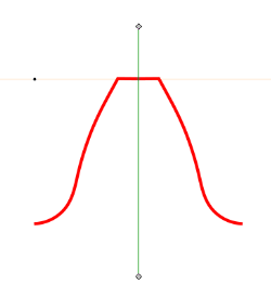
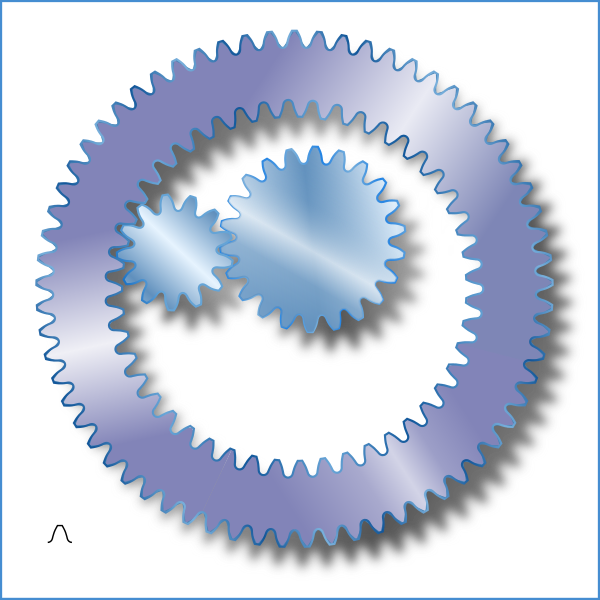
This is one of those times when you really have a perfect tool for a job in the development build that apparently will not be available soon - perhaps ever - in the regular release. I used mirror symmetry (and spiro spline) to create this:
which I applied to a variety of circular paths (not ellipses) to get this:
(You can see the tooth pattern path in the bottom left.)
The stretched options and width in units of length should be avoided! Or the teeth of your gears will become differently sized and not mesh.
After applying the pattern switch to the and select all the nodes of the circolar path and scale usng alt - < and alt - > to close the gap. You have to scale this way because scaling with the selector results in the post effect path being scaled, once again destroying the tooth size match...
The internal gear was done by simply reversing the path.
The SVGZ filesize without any frills was only 56KB.
This is one of those times when you really have a perfect tool for a job in the development build that apparently will not be available soon - perhaps ever - in the regular release. I used mirror symmetry (and spiro spline) to create this:
- image1459.png (5.91 KiB) Viewed 5950 times
- gearup.png (181.16 KiB) Viewed 5950 times
The stretched options and width in units of length should be avoided! Or the teeth of your gears will become differently sized and not mesh.
After applying the pattern switch to the
and select all the nodes of the circolar path and scale usng alt - < and alt - > to close the gap. You have to scale this way because scaling with the selector results in the post effect path being scaled, once again destroying the tooth size match...The internal gear was done by simply reversing the path.
The SVGZ filesize without any frills was only 56KB.
- Attachments
-
- gearupnoshadow.svgz
- (55.72 KiB) Downloaded 194 times
Last edited by druban on Fri Jul 27, 2012 3:39 pm, edited 5 times in total.
Your mind is what you think it is.
Re: how to simplify this - not so much as in Path/Simplify m
@Maestral: "Perhaps this extension would be more appropriate?" - wow, yes, thanks! Even though not perfect, I can maybe also look at the code and maybe change it a bit if I have time and/or want to try that ! Thanks!
"Also, this guy has an interesting..." -- I'll look at it tomorrow - gotta sleep now, looks very interesting, thanks a lot!
@druban: Wow, thanks a lot for showing how a "pro" would do it... It supports me in learning inkscape better - a shame I didn't learn it years ago (I stayed for too long with xfig, now I'll use inkscape in the future, that's for sure)...
1) "preference for simplification threshold - how much each use of the command affects the drawing - in preferences>behavior. " -- actually no, it was under "Misc" and then "simplification threshold", I found it after 10 minutes... And this really helped a lot and improved what I came up with dramatically !!! Quick and easy (for a lazy guy like me). However, you also write more interesting things:
2) Are you saying that "development build that apparently will not be available soon - perhaps ever - in the regular release. I used mirror symmetry (and spiro spline)..." ..... that I cannot do what you did without the development build? I tried to look for "mirror symmetry" and googled it, but it was supposed to be in the path-menu - however it isn't there... Do you recommend that I download the development build and try it out?
3) I also downloaded your " gearupnoshadow.svgz " - looks GREAT ! This is much better than what I started out with... I don't understand this: "The stretched options and width in units of length should be avoided! Or the teeth of your gears will become differently sized and not mesh. After applying the pattern switch to the and select all the nodes of the circolar path and scale usng alt - < and alt - > to close the gap. " - it requires me to have the development version, because I couldn't find the "mirror symmetry" menu option, is that correct? So I'm back at question 2, asking whether or not it's a good idea to spend some time and download this version...?
Anyway - it looks great ! Thanks - I'll never go back to xfig after this. And it's free, amazingly enough
Re: how to simplify this - not so much as in Path/Simplify m
newsboost wrote:actually no, it was under "Misc" and then "simplification threshold
Ha, well, now you know where you will find it in the development build if you get it...
newsboost wrote: Do you recommend that I download the development build and try it out?
Well, you have little to lose by doing so, Inkscape crashes are very discreet and do not affect your system at all. Just save frequently.https://skydrive.live.com/?cid=09706d11303fa52a&resid=9706D11303FA52A!217&id=9706D11303FA52A%21217
newsboost wrote:The stretched options and width in units of length should be avoided! Or the teeth of your gears will become differently sized and not mesh. After applying the pattern switch to the nodetool and select all the nodes of the circular path and scale usng alt - < and alt - > to close the gap ... it requires me to have the development version, because I couldn't find the "mirror symmetry" menu option, is that correct?
No, this is in reference to the 'pattern on path' live path extension dialog box. When you are going for something like a gear that has to have the same size teeth as another gear it does not work to stretch the pattern to make it fit, nor does it make sense to have a gap in the gear at one point, so you have to disable the first option and size the path you are putting it on carefully to make sure its length (circumference in this case) is a whole number multiple of your tooth width, does that make sense?
The second option scales the width proportional to the length and actually would not make any difference if you are not stretching the path so i don't know why I mentioned it...
The ALT + > and ALT + < keypresses ar for precisely increasing and decreasing the size of an object. You have to use them with the
and 'selecting all nodes' on an object that has a path effect to scale the 'before' path ('base' path?) or else you will scale the result ('final path?'). In the file that I uploaded, try this - select one of the gears. Switch to the
. See the circular path that appears? do ctrl-A and then press Ctrl + >. see the path got bigger, and there's more teeth on the gear, but there's probably a gap? Now size it up slowly with Alt + >. Zoom in  so you can see the gap, but don't forget to reselect all when switching back to the Scale it up so the gap is tiny. If you go too far there'll be another gap but you can just use alt + < to go back.
To avoid getting a lot of paths if you do object to paths (no reason to, really) check 'fuse nearby ends' in the path effects dialog.
It's complicated but the best thing to do is to sit down with it and just try tweaking some values.
Your mind is what you think it is.
Re: how to simplify this - not so much as in Path/Simplify m
Well, you have little to lose by doing so, Inkscape crashes are very discreet and do not affect your system at all. Just save frequently.https://skydrive.live.com/?cid=09706d11 ... A52A%21217
Thanks - maybe in the weekend I'll try it out - I got a few things to do first.
No, this is in reference to the 'pattern on path' live path extension dialog box. When you are going for something like a gear that has to have the same size teeth as another gear it does not work to stretch the pattern to make it fit, nor does it make sense to have a gap in the gear at one point, so you have to disable the first option and size the path you are putting it on carefully to make sure its length (circumference in this case) is a whole number multiple of your tooth width, does that make sense?
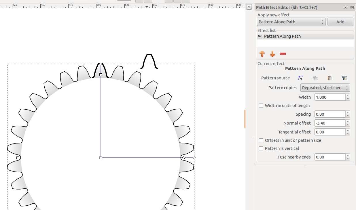
Ah, now I see - It's the "Path Effect Editor (shift+ctrl+7)" and I have to make a circle, transform it to path and then place one tooth on the circle-path, copy pattern and paste it and the repeat - then it makes good sense what you write and I think I can reproduce it now
Very nice - much easier than manually copying and rotating each teeth! I understand this with ALT + > and "<" respectively... I don't think I have this "fuse nearby ends" - maybe it's in the development version only, I guess. Anyway, I could probably add a segment or I can live with this in any case...
I'll look at the youtube movie from maestral later when I'm alone (because I'm in a shared office) - thanks all, I think currently I more or less have a good idea about what to do - I just need some time to play around with it
Great with good support here - and now I don't have to wait until moderators approve my postings, that's nice... Must've been quite some spammers in here since moderation is required (maybe only for new users)... Anyway, thanks all - I'll play around with it and ask a new question if anything comes up...
Re: how to simplify this - not so much as in Path/Simplify m
newsboost wrote:...place one tooth on the circle-path, copy pattern and paste it and then repeat - then it makes good sense what you write and I think I can reproduce it now
I am not sure what you are doing but it sounds like a HUUUGE amount of work!
These are the steps i used:
1. Draw a path for the geartooth. Copy it to the clipboard (ctrl-C)
2. Draw a circle with the ellipse tool. Convert it to an object (this is AFAIK the only way to use
for sizing after the effect has been applied, ~suv??)3. Open the Path Effects editor, with the circular path selected.
4.Pick the 'repeated' option from the pattern copies dropdown menu.
5. Pick the 'paste path' option for 'pattern source'.
6. Switch to the node tool to edit the circle path on canvas to close the gap.
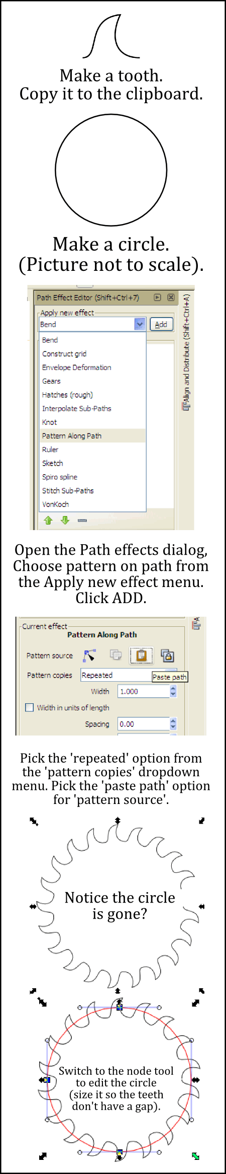
- rect3165.png (71.91 KiB) Viewed 5903 times
Your mind is what you think it is.
Re: how to simplify this - not so much as in Path/Simplify m
druban wrote:2. Draw a circle with the ellipse tool. Convert it to an object (this is AFAIK the only way to use :tool_node: for sizing after the effect has been applied, ~suv??)
If you use 'Repeated, stretched' for the 'Pattern copies' option, there is no need to «edit the circle (size it so the teeth have no gap)».
(Works for me also with the circle btw - I can resize the circle using the circle tool, while keeping the 'Pattern along Path' LPE in effect and live-updating. Current trunk though gives me a better result when using the circle with 'Repeated, stretched' than stable 0.48.3.1: with stable, the ends don't seem to meet correctly unless the circle has been converted to path before applying the path effect.)
Off topic:
No one recommended to use the Gears LPE for intermeshed gears?Re: how to simplify this - not so much as in Path/Simplify m
~suv wrote:If you use 'Repeated, stretched' for the 'Pattern copies' option, there is no need to «edit the circle (size it so the teeth have no gap)»
Yes! But as I understand it, the point of gear diagrams is that the teeth of ALL the gears have to be exactly the same size. Since the repeated stretched option scales the width of each tooth - and checking the '... in terms of option' just scales the whole tooth up. Am I missing an option here?
~suv wrote:I can resize the circle using the circle tool
I don't know any way to use fine adjustment (i.e. alt + > type) with the ellipse tool handles. If you zoom in on the control handle, you might not be able to see the gap anymore... Is there some way to select the handle and use alt + arrow keys?
~suv wrote:Off topic:
No one recommended to use the Gears LPE for intermeshed gears?
The gears LPE is the best way to go specially for many intermeshed gears - but the OP did not like the tooth profile. Is there some GUI way to change the tooth shape?
Your mind is what you think it is.
Re: how to simplify this - not so much as in Path/Simplify m
druban wrote:newsboost wrote:...place one tooth on the circle-path, copy pattern and paste it and then repeat - then it makes good sense what you write and I think I can reproduce it now
I am not sure what you are doing but it sounds like a HUUUGE amount of work!
These are the steps i used:
1. Draw a path for the geartooth. Copy it to the clipboard (ctrl-C)
2. Draw a circle with the ellipse tool. Convert it to an object (this is AFAIK the only way to use
3. Open the Path Effects editor, with the circular path selected.
4.Pick the 'repeated' option from the pattern copies dropdown menu.
5. Pick the 'paste path' option for 'pattern source'.
6. Switch to the node tool to edit the circle path on canvas to close the gap.
Aah, that's 99% of what I did
That explains why I had an extra tooth on the circle path, after I made the pattern... What I did is exactly like you here described, exept that I (for some reason) thought that the first tooth had to be on the circle pattern. Then I copied it and pasted it and ended up with 1 extra tooth - and then I deleted this extra tooth... Anyway - thanks a lot...
I'll just reply to the other helpful answers in a minute in another post(s)...
Re: how to simplify this - not so much as in Path/Simplify m
druban wrote:~suv wrote:If you use 'Repeated, stretched' for the 'Pattern copies' option, there is no need to «edit the circle (size it so the teeth have no gap)»
Yes! But as I understand it, the point of gear diagrams is that the teeth of ALL the gears have to be exactly the same size. Since the repeated stretched option scales the width of each tooth - and checking the '... in terms of option' just scales the whole tooth up. Am I missing an option here?
No, you're completely correct... There is ONE PARTICULAR "pitch circle diameter" for ONE PARTICULAR set of number of teeth and module... In fact: The pitch circle diameter is number of teeth times the module. So if you get a tooth using say module 5, then you choose the number of teeth and multiply the two numbers and there's the pitch circle diameter... Everything else is WRONG and it'll look wrong. It's great that you understood that that the tooth shouldn't be resized - I wanted the tooth to look completely correct as it would have been made in the real world...
druban wrote:~suv wrote:I can resize the circle using the circle tool
I don't know any way to use fine adjustment (i.e. alt + > type) with the ellipse tool handles. If you zoom in on the control handle, you might not be able to see the gap anymore... Is there some way to select the handle and use alt + arrow keys?~suv wrote:Off topic:
No one recommended to use the Gears LPE for intermeshed gears?
The gears LPE is the best way to go specially for many intermeshed gears - but the OP did not like the tooth profile. Is there some GUI way to change the tooth shape?Now I look back at the OP post and it's actually the EXTENSION Render > gears (not a very useful one, and buggy) that OP did not like! Oops.
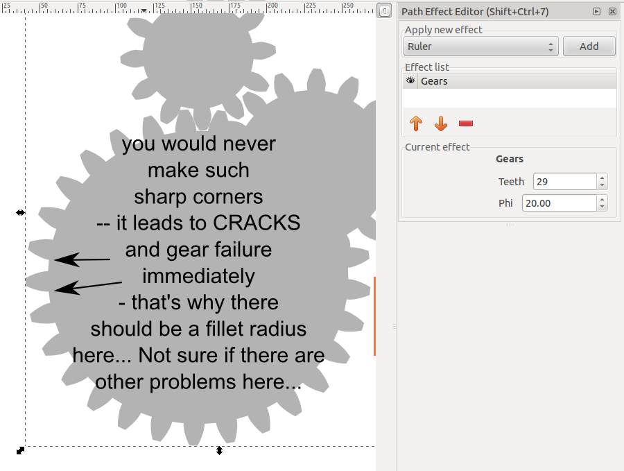
Hi, thanks for telling that there's another gear option - in the LPE menu. But now I tried it out (I'm using stable version, not developer if it means anything) and I don't like that option too... It's not a correct gear - it's a "children gear"... In the real world you would never manufacture a gear like what I've seen from the LPE-menu. It leads to (in theory) infinite high stress concentrations in a very small area and that initiates cracks and failure. All professionels will spot this immediately if they see such a gear... That's why I wanted to use my own gear... Thanks for the comments, though.
- Attachments
-
- gear_sharp_corner.png (96.94 KiB) Viewed 5862 times
Re: how to simplify this - not so much as in Path/Simplify m
newsboost wrote:druban wrote:~suv wrote:If you use 'Repeated, stretched' for the 'Pattern copies' option, there is no need to «edit the circle (size it so the teeth have no gap)»
Yes! But as I understand it, the point of gear diagrams is that the teeth of ALL the gears have to be exactly the same size. Since the repeated stretched option scales the width of each tooth - and checking the '... in terms of option' just scales the whole tooth up. Am I missing an option here?
No, you're completely correct... There is ONE PARTICULAR "pitch circle diameter" for ONE PARTICULAR set of number of teeth and module... In fact: The pitch circle diameter is number of teeth times the module. So if you get a tooth using say module 5, then you choose the number of teeth and multiply the two numbers and there's the pitch circle diameter... Everything else is WRONG and it'll look wrong. It's great that you understood that that the tooth shouldn't be resized - I wanted the tooth to look completely correct as it would have been made in the real world...
Ok - please tell me which of the two gears in the attached file is WRONG, and which one is CORRECT (while keeping in mind that 'Pattern along Path' doesn't use the same parameters as the specialized Gear tools).
(The geometry of the pattern source (tooth) is taken from newsboost's original SVG file).
- Attachments
-
- compare-1.svg
- (15.24 KiB) Downloaded 180 times
Re: how to simplify this - not so much as in Path/Simplify m
Regarding the attachment in newsboost's last reply, which says "you would never make such sharp corners -- it' leads to CRACKS and gear failure immediately - that's why there should be a fillet radius here....Not sure if there are other problems here...". I don't think the gears created with either Inkscape's Gear extension or Gears LPE are meant to be technically correct, or comparable to CAD or any sort of industry specs. I would think, that realistically, any sort of program or tool designed for technical drawing or blueprints, or something, would have many, many more options and settings!
Off topic:
Maestral, I don't see that extension for different kinds of gears in the Extension Repository. Do you know if it's slated to appear in a future version of Inkscape?Basics - Help menu > Tutorials
Manual - Inkscape: Guide to a Vector Drawing Program
Inkscape Community - Inkscape FAQ - Gallery
Inkscape for Cutting Design
Manual - Inkscape: Guide to a Vector Drawing Program
Inkscape Community - Inkscape FAQ - Gallery
Inkscape for Cutting Design
Re: how to simplify this - not so much as in Path/Simplify m
~suv wrote:Ok - please tell me which of the two gears in the attached file is WRONG, and which one is CORRECT (while keeping in mind that 'Pattern along Path' doesn't use the same parameters as the specialized Gear tools).
(The geometry of the pattern source (tooth) is taken from newsboost's original SVG file).
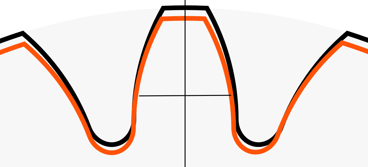
I'm not sure I understand what you're trying to say... I put the two gears into each other:
- comparison.png (52.31 KiB) Viewed 5822 times
And I could see that the little gear is more "to the left" than to the right gear, when I compare the little and the big gears. So I inserted a vertical line to see if there was any clear unsymmetry - I would guess that the black (big gear) is the correct one, because it's more symmetric. When I make horizontal lines, it's clear that something is unsymmetric about the little gear... You're asking which gear is WRONG and which is CORRECT. What is your definition of right and wrong ? You could - admittely - cheat anyone by just making small changes. But what's the point in making something a bit wrong, if you can import the correct coordinates and do everything correct ? Sorry if I don't understand the point here...
I used some imported coordinates, because I knew they were correct in the document I'm writing about. So why use something that I know is wrong, if I want it to be right? Why not just use what I know is right? Admittely, in this case it's hard to see the difference between the two gears. I couldn't make this fillet radius with this builtin-tool but it's great that I still got it like I wanted... Thanks...
Re: how to simplify this - not so much as in Path/Simplify m
Off topic:
brynn wrote:Maestral, I don't see that extension for different kinds of gears in the Extension Repository. Do you know if it's slated to appear in a future version of Inkscape?
While not being Maestral, I'll try to answer nevertheless: that enhanced version was already filed in the bug tracker (to be included in trunk). Since a similar enhancement had been provided earlier and subsequently was accepted into the developement branch, further processing has stalled a bit (since the two variations of the same enhancement would have to be combined into one).
For the curious:
Re: how to simplify this - not so much as in Path/Simplify m
brynn wrote:Regarding the attachment in newsboost's last reply, which says "you would never make such sharp corners -- it' leads to CRACKS and gear failure immediately - that's why there should be a fillet radius here....Not sure if there are other problems here...". I don't think the gears created with either Inkscape's Gear extension or Gears LPE are meant to be technically correct, or comparable to CAD or any sort of industry specs. I would think, that realistically, any sort of program or tool designed for technical drawing or blueprints, or something, would have many, many more options and settings!Off topic:Maestral, I don't see that extension for different kinds of gears in the Extension Repository. Do you know if it's slated to appear in a future version of Inkscape?
Yes, agreed. I'm just happy that I could easily import the coordinates and then helpful people in here told me how to simplify or reduce the number of nodes to something that's usable...
There was a post earlier about someone who did something very interesting with python (making his own extension). There's a link to that file in this thread, which I find very useful / inspiring - however I need a bit more time to dig into how this user-contributed extension was made... And most people probably don't care if the gear is correct or not - it's just, for my current document, I want it to be "correct" using own coordinates that I trust. But a good tool has many ways to accomplish different tasks - it's great that I hadn't any coordinates, then I could still make something, though the sharp corners (no fillet radius) doesn't look good in my opinion... But I guess it's a matter of personal preferences - I think inkscape is great and hope to become much better in the coming months
Re: how to simplify this - not so much as in Path/Simplify m
~suv wrote:Off topic:brynn wrote:Maestral, I don't see that extension for different kinds of gears in the Extension Repository. Do you know if it's slated to appear in a future version of Inkscape?
While not being Maestral, I'll try to answer nevertheless: that enhanced version was already filed in the bug tracker (to be included in trunk). Since a similar enhancement had been provided earlier and subsequently was accepted into the developement branch, further processing has stalled a bit (since the two variations of the same enhancement would have to be combined into one).
For the curious:
Oh, yes - exactly... I think this guy is correct about his ideas and that developers can use his improvements...
Re: how to simplify this - not so much as in Path/Simplify m
I did not define this - you did, in your earlier comment, dismissing the option 'Repeated, stretched' by claiming that it produces wrong gears (see what I quoted when asking the question). But anyway: I apologize for nitpicking - let's stop here and agree that 'Pattern along Path' LPE is not a tool intended to create technically correct and optimized professional gears suited for production, and that it would be nice to have more options for the specialized gear tools to allow to create gears which at least pretend to be more professional (with fillets instead of sharp corners). I won't agree on degrading Inkscape into a Child's toy though ;-) (SCNR).newsboost wrote:You're asking which gear is WRONG and which is CORRECT. What is your definition of right and wrong ?.
(JFTR: the bigger one, to the left, was created with the pattern source 'Repeated, stretched' (with '[x] Width in units of length'), applied to a circle. The smaller one to the right was based on druban's instructions: pattern source 'Repeated' on a path (originally a circle of the same size and converted to path), and then that skeleton path scaled in the node tool until the start and end points of the repeated pattern approximately meet).
Re: how to simplify this - not so much as in Path/Simplify m
~suv wrote:I did not define this - you did, in your earlier comment, dismissing the option 'Repeated, stretched' by claiming that it produces wrong gears (see what I quoted when asking the question). But anyway: I apologize for nitpicking - let's stop here and agree that 'Pattern along Path' LPE is not a tool intended to create technically correct and optimized professional gears suited for production, and that it would be nice to have more options for the specialized gear tools to allow to create gears which at least pretend to be more professional (with fillets instead of sharp corners). I won't agree on degrading Inkscape into a Child's toy thoughnewsboost wrote:You're asking which gear is WRONG and which is CORRECT. What is your definition of right and wrong ?.(SCNR).
(JFTR: the bigger one, to the left, was created with the pattern source 'Repeated, stretched' (with '[x] Width in units of length'), applied to a circle. The smaller one to the right was based on druban's instructions: pattern source 'Repeated' on a path (originally a circle of the same size and converted to path), and then that skeleton path scaled in the node tool until the start and end points of the repeated pattern approximately meet).
Oh, now I understand your point.. Inkscape is very professionel - I'm just not so happy about the included "gear-drawing-capabilities" because the gear (without fillet radius, at least) looks like something that easily breaks - like a childrens toy... But now I just googled and there's a lot of gears that don't have this fillet radius... Here's what can easily happen if the fillet radius is too little http://tinyurl.com/d4w9698 - once there's a small crack, it's absolutely worthless - there's only a short time left before one have to replace it all, cannot work with 1 missing tooth because then the next crack in the neighbouring tooth comes pretty quick...
I now understand the difference between the two gear-drawing methods (and that it's easy to cheat/fool people with stretching), thanks. Well, maybe I don't fully understand it, but I just did some testing based on your example and I totally agree that it's hard to see the difference. My intention was just to make it "as correct as possible" so there's one particular pitch circle diameter for one module and a given number of teeth and that is a constraint I wanted to use - for this gear it should work without stretching (though I admit I didn't try to calculate the exact correct diameter for this - maybe another time I should give a try - the gear I provided ideally should have 29 teeth - if I remember correct, the module is 5 - so the ideal diameter should be 29*5 units (I didn't try this, though - I admit)...
I would agree that it's pretty much impossible to see the difference in your example, however with you scale and stretch maybe the difference would be obvious at some other diameter.... But I think that it would maybe be obvious that something is wrong, if you're trying to make a gear with either maybe 8-10 teeth or more than 60 teeth using the profile I came up with... It's made for 29 teeth... If the number is (much) different, a new tooth profile has to be made... Anyway, I'll just stick to my current solution (although not 100% correct, because I didn't try to get the exact diameter, I was lazy and I'm still an inkscape noob - next time, though, I promise I'll do it 100% correct, if there ever is a next time)... I would just be a bit cautionous about this "stretching" because the gear profile was made for a particular diameter (29*5) and a particular number of teeth (29) and using these values, in theory I think stretching is not necessary...
Anyway: Stretching is a good quick solution if accuracy is not 100% required, I understand that now...
Thanks for making it clear (that the difference is actually smaller than I thought, between not stretching and stretching)...
Re: how to simplify this - not so much as in Path/Simplify m
~suv wrote:I did not define this - you did, in your earlier comment, dismissing the option 'Repeated, stretched' by claiming that it produces wrong gears (see what I quoted when asking the question). But anyway: I apologize for nitpicking - let's stop here and agree that 'Pattern along Path' LPE is not a tool intended to create technically correct and optimized professional gears suited for production, and that it would be nice to have more options for the specialized gear tools to allow to create gears which at least pretend to be more professional (with fillets instead of sharp corners). I won't agree on degrading Inkscape into a Child's toy thoughnewsboost wrote:You're asking which gear is WRONG and which is CORRECT. What is your definition of right and wrong ?.
(JFTR: the bigger one, to the left, was created with the pattern source 'Repeated, stretched' (with '[x] Width in units of length'), applied to a circle. The smaller one to the right was based on druban's instructions: pattern source 'Repeated' on a path (originally a circle of the same size and converted to path), and then that skeleton path scaled in the node tool until the start and end points of the repeated pattern approximately meet).
Ok, now I must correct myself:
I couldn't make it work with a circle diameter of 29*5 - and without stretching. I had to stretch to get 29 teeth (an no gap):
- new_repeat_stretch_test.png (97.13 KiB) Viewed 5764 times
I left a thick black tooth where I knew it should be and made a circle around the center I knew should be the center. Then I had to change the "Normal offset" in order to hit the old tooth.
Correction: I think maybe the tooth data I provided isn't a simple tooth after all... Maybe it has this "profile shift", meaning that I cannot use the circle with diameter = 29*5... Anyway, who cares... It still looks good. I'm not an gear expert so I cannot make the gear tooth profiles myself (maybe I got a program however, that can generate it, however it's too much work now, I already have something that looks decent and it's enough for now)...
Gotta sleep now / soon... Will check for replies tomorrow...
- Attachments
-
- test (1).svgz
- (11.52 KiB) Downloaded 203 times
Re: how to simplify this - not so much as in Path/Simplify m
Now I`m confused....
You were working with Xfig but you were not satisfied with the result, so you tried to do the same thing with the Inkscape, right?
Well, if none of these approaches presented in this post fits your needs, what kind of gears you are looking for?
How convincing these are?
Ages ago I worked with CAD but could not completely recall how I did gears back in that time... so I looked over the web:
How does it looks like?
As I mentioned before, you`ll have to do some math if you need a really precise technical drawing of the gear. Especially if it would be really produced, in the real world with all of the forces, frictions.. and all of these constants and variables which goes along with the real world mechanics. It`s not just because I say so, but because real world says so ,) All these things, which are determining the wear of gear, should be calculated and then applied into the technical drawing. Shall I mention how much influence to the whole thing goes with the specifications of metals and alloys?
So, could you please explain a bit further for what purpose do you need these drawings of gears and how precise they have to be? I`m pretty much sure you`ll be provided with the alternate solution.
<<< click! - but, those with a cheaper tickets should go this way >>>